Friday 17 December 2010

The End!

Final airtightness test carried out.
Now improved to 2.8 m3/m2 at 50 pa!
Again some sealing required.
There is air loss where we know to have problems from both detailing and execution of the works. Although the latter we will have to accept as how far does one go!!!
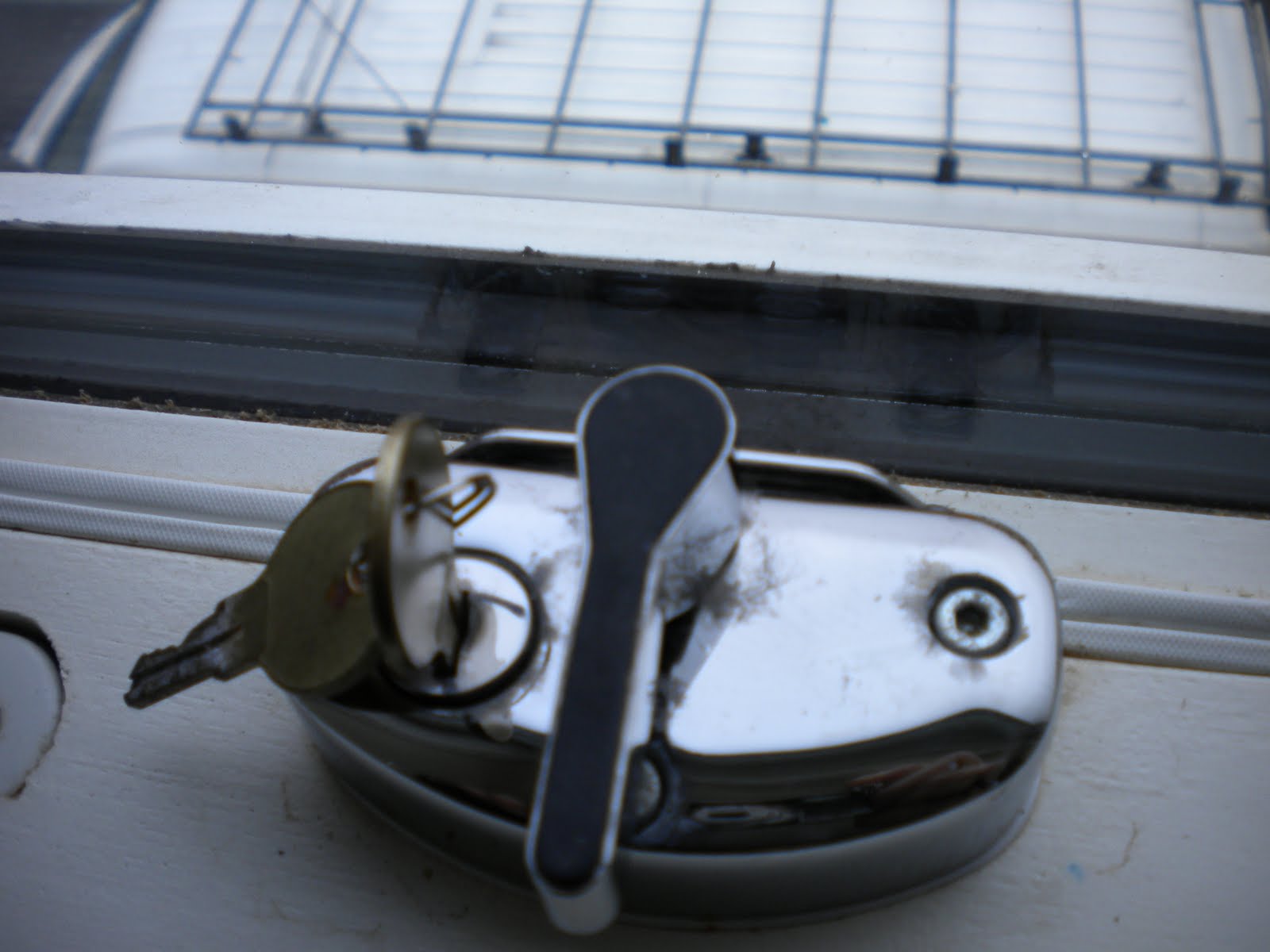
Air leakage occurred in the front window frames, around the sash fasteners. These are a vertical sliding sash design. This appears to be a detailing/manufacturing problem.
We will be notifying the manufacturer of our findings.
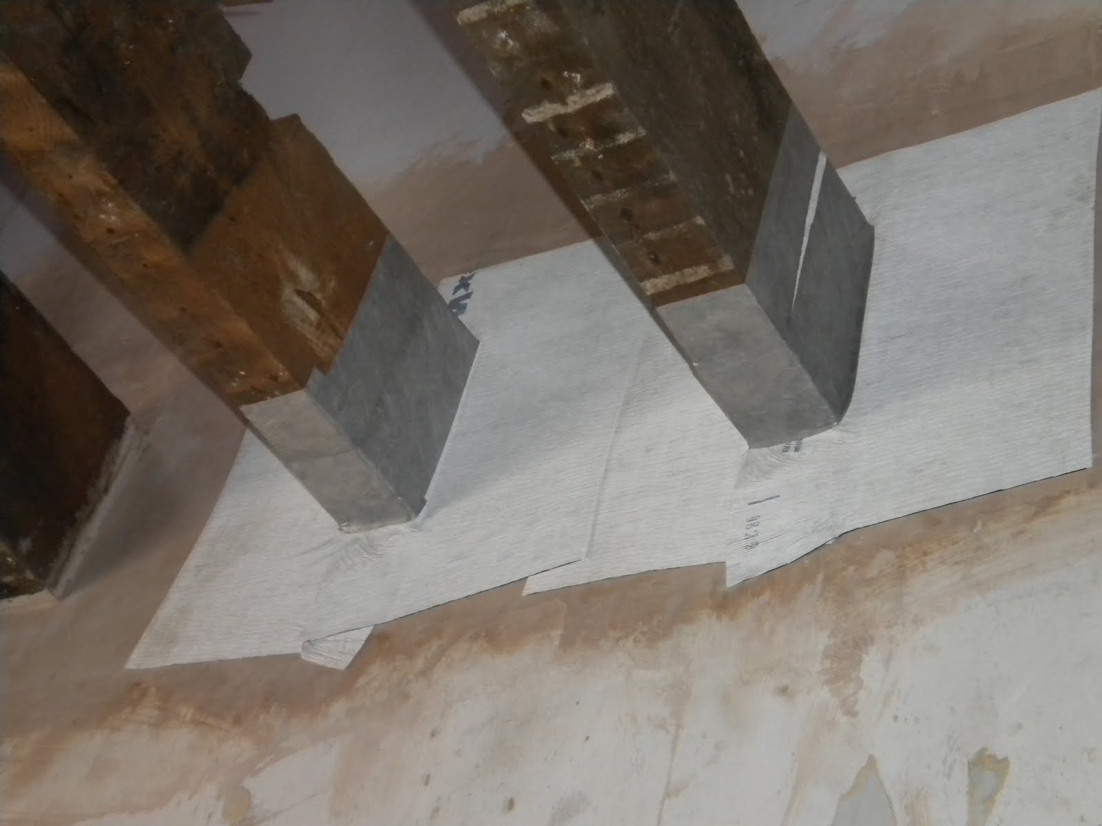
Leakage was noted at socket outlets and at 1st floor skirting/floor junctions.
The areas identified were retro sealed as best as possible.
It will be difficult to ascertain the air loss path at these locations.
There was a substantial leakage in the bathroom services cupboard.
This was an oversight where a controlled penetration pipe sleeve had not been sealed! This has been sealed, although could not confirm what the impact of this was as the testing company had to leave.
Predict a final official air test result, when carried out by the EST, to be nearer 2.5 m3/m2 at 50 pa.
Slightly frustrating to know the issues that exist, we were not that far off realistically in achieving PassivHaus air tightness level.

Wednesday 24 November 2010

COMPLETE!!!!!!

Decoration complete.

Minor finishing off tasks have dragged on a little, but we are there.

Property complete.

Friday 19 November 2010

I'm sure I can see the finish?

Heating install completed and commissioned.

Some minor commissioning issues with a leak on solar pipes on the roof. This was easily addressed.

Wattbox second fix complete and commissioned.
Operating as planned.

External works complete.

Thursday 11 November 2010

Still 2nd fixing

Second fix work continues.

Some electric cables were lost while boarding over ceilings and walls. This caused some minor opening up to re locate cables, in two or three locations.

Decoration continues.

Friday 5 November 2010

2nd Fix Electrics

Second fix electrics commenced.

There was some ambiguity with regards to the securing of the light fittings which was clarified by the lighting supplier.

The down-lights in the pod were substituted for surface light fittings. Although not an ideal solution, it was adequate.

Internal decoration commenced on site. Although this was a little premature, we needed to gain some time back.

Wednesday 3 November 2010

Waterproof testing

At the end of September, EMH team members visited a couple of other retrofit projects in the North east of England to assess and benchmark progress on project implementation and to discuss any similar problems arising. Project Cottesmore has similar project members, managers and a significant overlap in the supply chain with the projects at Greenford Road in Newcastle and the Isos property in North Shields. The image show the property in Newcastle and the detailing on the roof and bay window produced as an off-site pod. Looks waterproof from the outside!

Friday 29 October 2010

And so the work continues...

First fix heating and plumbing commenced.

Heating pipework is in micro-bore.

Solar collector pipework enters roof void between the pod an party walls via a proprietary flexible slate on roof. These fall outside of the airtightness membrane and enter on the first floor living space rear-elevation.

Care needed to be taken that the breach in the airtightness is controlled and carefully resealed.

Furthermore, pipework from the pod for the heating and the overflow for the MVHR also breached the airtightness membrane. The location is awkward and a lot of effort was taken to ensure that resealing was satisfactory. These pipes enter the bathroom services cupboard via a sealed duct.

The boiler flue was sleeved through a duct to outside.
This sleeve was sealed around the brickwork and the airtightness membrane. When the boiler flue is inserted the gap between the flue and the duct will be sealed internally and externally ensuring airtightness.

Second fix joinery commenced.
Fire doors within the property were cut from fire blanks to take into account non standard openings.

The kitchen was installed as per agreed layout.
The cooker-hood extractor which was integrated as part of the MVHR was installed and attached to the ducting.

A cupboard was formed in the front bedroom to allow for storage and an additional cupboard was formed around the MVHR unit.

Site visit takes place from Kingfisher Group to look at pod and retrofit works.

Wednesday 13 October 2010

Pre-Completion Air Test

Some skimming work commences within the property.

The services cupboard is constructed in the bathroom.
It became apparent because of limited space that it would be very tight to incorporate all the necessary components, which included the boiler, twin-coil hot water cylinder, expansion vessels, and solar pump amongst other things.

An intermediate air tightness test was carried out;

The test indicated an air tightness reading of 3.4 m3/m2 at 50 pa.

This was quite a result, as the pre start reading was 15.1 m3/m2 at 50 pa. Areas were identified where some leakage was occurring, most of which could be addressed with some additional work and sealing up. However as previously suspected the metal to metal joints of the underside of the pod structure that were inaccessible will be impossible to fully address.

Once the property is fully plastered the test should improve. We will have to take a hit on this.

EMHA board members attend site for a visit of the retrofit property.

Thursday 7 October 2010

Are we there yet?

The timber stud around the windows to form the reveal were set approximately 20 degrees out of square to give us a splay detail as described previously.

Because of the limited timber section on the windows, fixing the plaster board proved difficult. The solution was to fit a 10mm timber bearer around the perimeter of the windows. Plaster board could be carefully fixed to this and the timber stud after insulation was stuffed behind the reveal board.

The MDF window boards were secured in a similar manner.

The same situation occurred on the front elevation windows where the timber section was exceptionally limited. The solution was to solvent fix white tile trim along the perimeter. This would allow plaster board to be trapped at this point and secured to the timber stud.

The sealing and air tightness work has taken a considerable amount of time, much more than anticipated. The manual labour element of ensuring air tightness continuity and sealing/patching can account for much of the time, as well as additions discovered when stripping out the property.

There has been a continuous learning process for the project team and operatives. They now have a greater appreciation of what and why it is being done, than they did before starting on site.

Tuesday 5 October 2010

Boxed In

The front door and rear door were installed and a fabric skirt was attached to the frames as per the window details.
The continuous airtight membrane caused a problem in the bathroom.
The membrane was running up the walls and to the underside of the ceiling. The ceiling was then to be lathed and plaster boarded. The problem was the light fittings again were deeper than the lath and plaster board by a considerable amount. This would mean that the membrane would need to be cut out.
The solution was to create a plywood box that would be fixed in between the ceiling joists at the light fitting locations.
This box would be lined with a membrane and sealed.
The seal would continue into the ceiling membrane ensuring continuity and airtightness.
The boxes effectively created a hood for the lights. The lights and the transformer easily fitted within these boxes.

Thursday 30 September 2010

Plastering Started

The front windows were installed.
These were sliding sashes in accordance with the design; assuming the property was in the conservation area.
The MVHR ducting was completed with all vents to each room going back to the MVHR unit.
Dot and dab plaster boards were applied to the walls in readiness for skimming.
Rockwool was filled inbetween studs prior to fixing the plaster board.
A reciprocal site visit was arranged at Newcastle and North Shields.
This allowed us to compare technical details and look at alternative solutions that were being carried out on different Retrofit for the Future competition properties.

Friday 24 September 2010

First Fix Electrics

First fix electrics commenced.
As well as the electric cable, data cable was fed to the various locations within the property. This cable was necessary for monitoring purposes which will be done via the Wattbox controller.
Furthermore cables for telephone, cable television, and satellite were fed to all the rooms. This was to eliminate the risk of the new tenant calling in media companies and creating holes through their installation.
Most cables were drawn through existing first floor joists and through the new timber studding on the external walls. The cables were protected by metal plates to eliminate damage in the timber stud.
The draw cables within the pod structure conduit appeared to be jammed.
Boards were exposed within the pod structure to gain access. This revealed some poor jointing of the airtightness membrane within the pod structure.
We tried to address these in situ and refitted the boards after drawing the cables.
Down lighters within the pod structure ceiling were deeper than the insulated plaster board and as a result the specified down lighters could not be fitted. Another solution would need to be sought.
The MVHR ducting runs were installed as specified.
The ducting did need to run through the airtightness membrane. Great attention was paid to ensure a good airtight seal at these points. Some adaptation had to be made to the ducting runs in order to ensure a good flow and continuity to the various rooms in the property.
The utility meter cupboard doors had been manufactured incorporating insulation and twin seals to maintain airtightness.
It was assumed that the interior of the meter cupboard was not airtight because of existing gas and electricity meters etc.

Friday 17 September 2010

MVHR

The under pod sealing to the rest of the property has taken a considerable amount of time.
It is not certain that this will be 100% airtight because of the omission of the skirt to the pod underside.
The solar collectors were installed onto the pre-fitted brackets on the roof in readiness for the pipework connection.
The existing joists which continue over the passageway have been filled with insulation in order to eliminate any cold bridging from the passageway ceiling.
The membrane was jointed and continued up the wall and over the joists in the new first floor living space as described before.
The MVHR was mounted on brackets within the pod.
This was mounted higher than anticipated because of the need of a condensate trap on the underside of the unit. This in turn had an impact on the connections to the external exhaust and intake vents which were previously fitted within the pod roof structure.

Thursday 9 September 2010

Commenced air tight membrane installation in utility area.

Attached membrane to dpm using bitumen tap. The membrane then folded down and first layer of 100mm pir insulation board put up against wall, hence further trapping the insulation at floor.

The fabric then was lifted up to the insulation board.

Membrane jointed as per manufacturer recommendation.

Internal corners neatly folded.

Second layer of 50mm insulation stood up in front of membrane. The membrane had to continue through ceiling and around joists into bathroom to maintain continuity. Membrane is neatly cut around individual joist ends and the sealing method used was similar to the sealing method used on the party wall.


Timber stud, constructed from 50mm x 50mm timber, is erected and installed in front of insulation and secured to floor and timber joists.
The skirt from the windows is jointed to the wall membrane using metallic tape.
The reveals were then sealed with flexi wrap tape to ensure 100% air-tight seal.

Because the reveals were very deep we decided to splay the reveals in order for more light to be allowed in. The timber stud will be made up to allow for this splay on the reveals.


We identified that an error had been made in not incorporating a continuity skirt from the pod to the rest of the house.

We attached ribbons of membrane to the best possible locations on the underside of the pod to the structure of the house. We had to accept that this would not be a perfect seal because we could not guarantee how well the metal structure was sealed on other metal sections.

This was further exacerbated by the fact that some services had to come through the air-tight membrane. Bitumen tape was used to seal as best we could.
Insulation was stuffed between the pod sides and gable end brickwork.

Wednesday 8 September 2010

Window Fitting - Air Tightness

Rear elevation windows installed.
Metal straps used to secure windows to openings.
Attached air tightness membrane ‘skirt’ to outside of frame allowing 300mm excess.

Membrane attached using agreed method of timber strip in mortar groove and double sided tape. This proved finicky and the strip split and not big enough section to take screws. Adapted method and eliminated use of timber strips.


Used double sided bitumen tape to attach to frame then additional layer of metallic tape to close off open edge. Pleats incorporated, two at each corner, to allow manipulation of membrane around corner reveals of openings in order to attach to wall membrane.


All rear windows fitted.
Some windows very tight for the actual openings. Some are little more generous. Would have preferred a more experienced person to measure up rather than a building surveyor.
Heads of windows will need to be foamed, insulated and cloaked off at soldier arches.

Friday 3 September 2010

Roof complete

Roof covering work is complete!!!

Vents for MVHR exhaust and intake from outside appear to be too close together.


Confirmed with suppler of the solution to have top vent as the exhaust. This solution should be adequate.

Brackets supplied for solar hot water panels are for a tiled roof not a slated.

Contacted supplier unfortunately cannot get the correct brackets to us soon enough. Requested manufacturer drawings for the brackets. Steel fabricators asked to make up brackets over night.

The roof recovering works have take longer than desired. With hindsight we would have requested a gang to carry out works over a week rather than one operative taking three weeks. Nevertheless finished product is good.

Thursday 2 September 2010

The start of air tight work

Adjustments are made to the second staircase to incorporate additional kite winder giving the extra required clearance. This is verified with the architect, and staircase to the pod is successfully installed.
Inter-joist plastering takes place on party wall to eliminate air loss potential between joists bearing onto party wall.
These areas would never have been plastered and it is apparent that voids exist. Plastering between joists should be sufficient to seal up holes and minimise paths of airloss. Decision taken to do a belts and braces approach to the joist ends. The joist ends are wrapped and sealed with flexi wrap tape having tested and developed a method on site.

Friday 27 August 2010

How much insulation?!

Insulation is laid down on the finished concrete floor in two layers of 150mm and 75mm. This is 25mm more than specified to take into account differences in floor level.
Tongue and grooved chipboard, 18mm, is laid on top of insulation with glued joints. This was then covered with 4mm ply for protection of surface for the duration of the remaining construction phase.
Ground floor to first floor staircase installed with relative ease, incorporating three kite winders at the top of the flight.
Staircase from first floor to second floor pod, issue has arisen in that in the original arrangement of the staircase opening in the pod floor and calculated rise means that there is not enough head clearance available.